Electric lock for automatic gate
I have an automatic gate and I needed to put an electric lock on it. To request a technician, it would be very expensive (material, displacement to home, hand labor, ...).
I decided to build an electronic device to create some sort of a delay in the electric current, since the gate only can be open after the electric lock be unlocked.
The gate's motors work with 220V AC and the electric lock uses only 12V AC, so it's necessary to use a transformer.
The idea is to use a capacitor and an inverter to create the delay in the current before arrived to the motors, this will be achieved using a relay.
I started with a very complex circuit and finish with a very simple one.
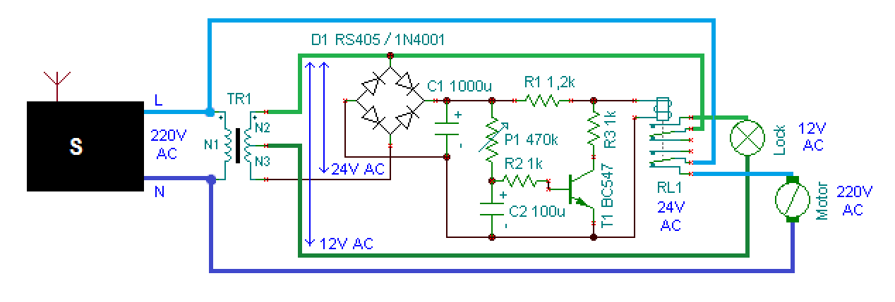
Circuit schematic
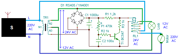
Schema of electric lock (click to enlarge)
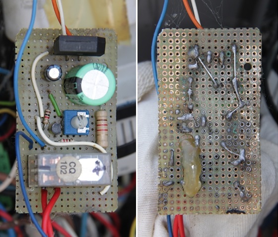
My implementation of electric lock schema
The two faces of the board, these images overlap.
Material
C1  : 1000µF to stabilize current

C2  : 100µF working as a timer with P1

R1  : 1.2 kΩ 1W - I used 1W for caution because of the hight current to teh relay

R2  : 1 kΩ

R3  : 1 kΩ

D1  : a bridge of 4 diodes or a integrated circuit (more compact) to rectifie the current

P1  : 470kΩ potenciometer to control de delay

T1  : BC547 - regular NPN transistor

TR1 : transformer with 2 output tensions (230V AC to 12V and 24V AC)

RL1 : relay with two-way

S   : this work like a black box, is the gate control system, 2 wires while the gates are moving
Considerations
The gate control system is represented by S, we can see it like a black box, I had 2 wires with power while the gates are moving, after we press the button to open them via a remote control.
The potentiometer controls the time which the lock is turned on, it works like a timer. When using a lower power the component values can be lower.
Using the inverse Laplace transformation we can calculate the value of capacitor and/or resistor, consider the circuit as a simple RC circuit, we can use these expressions.

See more about RC circuit and Laplace transformation on wikipedia.
I just used 24V because were available on transformer and I had a two-way relay of 24V.
This is not a perfect solution, but it seems to work fine. To use this circuit multiple times in a row, we need to wait a few seconds (less than 5 sec) after the power is turned off, to discard the capacitor.
With this schema the electric lock will "unlock" every time the motors are turned on, when they start to open (the goal) or start to close.
In the back of the board I put some glue to better isolate the current.
A friend of mine once told me: The engineer's job is complete not when you can't put more components, but when you can't remove more components...
 Disclaimer